Table of Contents
Magnetic circuit
| Stan Zurek, Magnetic circuit, Encyclopedia Magnetica, http://www.e-magnetica.pl/doku.php/magnetic_circuit |
Magnetic circuit - an assembly of components used as the means of manipulating magnetic field, or forming a path along which the magnetic field or magnetic flux is directed. In most magnetic circuits the magnetic field is not fully contained and also exist in the surrounding volume, thus forming a parasitic magnetic circuit, contributing to such effects as stray flux and flux fringing.1)2)3)

S. Zurek, E-Magnetica.pl, CC-BY-4.0
The name “magnetic circuit” is an analogy of “electric circuit”, in which the electricity is directed by using conductors and insulators. In a magnetic circuit, the magnetic flux is guided in a magnetic core made of high-permeability material, surrounded by other low-permeability media.
Magnetic circuits can be very complex, as dictated by the design and performance required of a given device. Often, the magnetic flux needs to be carried from the source of magnetic field to some other part. But in other devices, the magnetic field must be directed by magnetic shunts or magnetic shielding, away from sensitive equipment.
Various design techniques can be used for magnetic circuits. Simple cases can be approximated with sufficient accuracy with analytical equations. For more complex devices numerical methods such as finite-element modelling are required.4)5)

S. Zurek, E-Magnetica.pl, CC-BY-4.0

S. Zurek, E-Magnetica.pl, CC-BY-4.0
Components of magnetic circuit
Magnetic circuits can be simple or complex, and they can differ significantly from one device to the next, depending on the design and required performance, frequency of operation, range of temperatures, size, cost, etc.6) Some typical components of magnetic circuits are described below.
| → → → Helpful page? Support us! → → → | PayPal | ← ← ← Help us with just $0.10 per month? Come on…  ← ← ← |
Analogy to electric circuits

In some aspects, a magnetic circuit can be analysed as an analogy to an electric circuit supplied with a DC source.7)
In an electric circuit, the total voltage drop on the resistances $R$ will be the same as supplied by the voltage source $V$. The current $I$ in the circuit is directly proportional to the applied voltage and inversely proportional to the total resistance, according to the Ohm's law.
In an analogous magnetic circuit, the source is represented by the magnetomotive force MMF, also denoted with a stylised letter $\mathcal{F}$. If the excitation is applied from a magnetising coil, then its value is a product of the current in the coil and its number of turns (ampere-turns), so the resulting unit is amperes (A). If the source of magnetic field is a permanent magnet then the amount of excitation is quantified by the energy stored in the magnetic field of the magnet and its volume (and can also be expressed in ampere-turns if necessary).8)
The analogue of electrical resistance is the magnetic reluctance, denoted typically with a stylised letter $\mathcal{R}$, with the units of (A/Wb) or (1/H).
The analogue of electric current is the magnetic flux, denoted as $Φ$, with the units of (Wb) or (T·m2). The value of magnetic flux is directly proportional to the applied magnetomotive force and inversely proportional to the total reluctance present in the circuit.
If there are multiple sources, their effects are added in a similar way as in an electric circuit. Similarly, multiple reluctances are analysed similarly to electrical resistances.9)
| Electric circuit | Magnetic circuit | ||
|---|---|---|---|
| Quantity | Unit | Quantity | Unit |
| Voltage $V$ | (V) | Magnetomotive force $\mathcal{F}$ | (A) ≡ (A-turns) |
| Resistance $R$ | (Ω) | Magnetic reluctance $\mathcal{R}$ | (A/Wb) ≡ (1/H) |
| Conductance $G=1/R$ | (S) | Permeance $\mathcal{P}=1/\mathcal{R}$ | (H) |
| Current $I$ | (A) | Magnetic flux $Φ$ | (Wb) ≡ (T·m2) |
| Examples of calculations | |||
| $V = I·(R_1 + R_2)$ | $\mathcal{F} = Φ·(\mathcal{R}_1 + \mathcal{R}_2)$ | ||
| $I = \frac{V}{R_1 + R_2}$ | $Φ = \frac{\mathcal{F}}{\mathcal{R}_1 + \mathcal{R}_2}$ | ||
In this way, for many magnetic circuits, it is possible to simplify a three-dimensional problem effectively to a much simpler one-dimensional analysis, which can still provide sufficient engineering approximation.10)
However, the extent of this analogy is limited, because in the electric circuit the energy is dissipated in the resistance, but the the magnetic circuit the energy is not dissipated in the reluctance.
Reluctance and permeance
The concept of magnetic reluctance $\mathcal{R}$ is analogous to that of electric resistance $R$ (although the analogy is limited). For simple magnetic circuits the value can be calculated from its dimensions (area and length).
The calculations can be based on magnetic permeability $μ$ analogous to electric conductivity $σ$. It is also possible to use the concept of magnetic reluctivity11) $υ$ analogous to electric resistivity $ρ$.
| $$\mathcal{R} = 1 / \mathcal{P}$$ | $$R = 1/G$$ | |||
| from absolute permeability $μ$ (H/m) | from reluctivity $υ = 1/μ$ (m/H) | from conductivity $σ$ (S/m) | from resistivity $ρ$ (Ω·m) |
|
| Reluctance $\mathcal{R}$ (1/H) | Resistance $R$ (Ω) | |||
|---|---|---|---|---|
| $$\mathcal{R} = \frac{1}{μ} · \frac{l}{A} $$ | $$\mathcal{R} = υ · \frac{l}{A} $$ | $$R = \frac{1}{σ} · \frac{l}{A} $$ | $$R = ρ · \frac{l}{A} $$ | |
| Permeance $\mathcal{P}$ (H) | Conductance $G$ (S) | |||
| $$\mathcal{P} = μ · \frac{A}{l} $$ | $$\mathcal{P} = \frac{1}{υ} · \frac{A}{l} $$ | $$G = σ · \frac{A}{l} $$ | $$R = \frac{1}{ρ} · \frac{A}{l} $$ | |
| where: $l$ - length (m), $A$ - cross-sectional area (m2) | ||||
Example: for a part of a circuit with the length $l$ = 0.01 m, cross-sectional area $A$ = 0.001 m2. and relative permeability $μ_r$ = 1000 (which needs to be converted to absolute permeability), the reluctance can be calculated as $\mathcal{R} = \frac{1}{μ_r·μ_0} · \frac{l}{A}$ = 7.96·103 (1/H).
Air gap
| |
The term “air gap” refers to the non-magnetic part of the circuit, which is expected to carry substantial amount of the main magnetic flux in the circuit. It can be made of any non-magnetic, non-conductive material (and still be referred to as “air gap”).
In some magnetic circuits the presence of air gap is unavoidable and even a critical feature, especially in rotating machines (motor, generator), electromagnetic actuators and gapped electromagnets.
However, in other magnetic circuits the air gap can be eliminated or minimised, because its presence can be very detrimental. For this reason, magnetic circuits can be very broadly classified in two groups:
Closed magnetic circuit

Broadly speaking, a closed magnetic circuit is such in which the effect of the air gap can be neglected, at least in the first approximation,14) or such that the air gap is purposefully removed or minimised.15)
Such cores are typically used in power transformers, in which the magnetic properties of the core are similar around the whole magnetic path, or at least they can be treated as such from a macroscopic view (e.g. because of the homogenisation approach). The core can be made from a solid magnetic material (such as soft ferrite) or as a laminated stack (e.g. from electrical steel).
In a simple case of a single-phase device, the magnetic flux can be assumed to remain the same along the magnetic path, and thus if the cross-sectional area of the core is also constant, then the magnetic flux density is also the same throughout the core. For three-phase (and in general for poly-phase) devices the analysis is more complex, but otherwise analogous.
It can be assumed that the Ampere's circuital law holds and for a simple circuit:16)17)18)
| Ampere's circuital law in a closed magnetic circuit | |
|---|---|
| $$H = \frac{N·I}{l}$$ | (A/m) |
| where: $H$ - magnetic field strength (A/m) in the circuit, $N$ - number of turns of the magnetising winding (unitless), $l$ - magnetic path length of the circuit (m) | |
Closed magnetic circuits are used for measurements of magnetic properties of soft magnetic materials. For example:
- single-sheet tester (SST) 21)
Measurements with the Epstein frame method are used for classification of grades of electrical steels.
In the SST method the specimen-under-test has a different cross-sectional area than the magnetic yoke which provides a magnetic “short-circuit” so that all the magnetomotive force can be assumed to be dropped across the sample under test.


Open magnetic circuit

An open magnetic circuit is such in which the presence of an air gap cannot be neglected, or in which the air gap (or other non-magnetic discontinuity) is on of the main features of the circuit.22)

The presence of an air gap changes the effective permeability of the whole circuit because soft magnetic materials have high relative permeability ($μ_r \gg $ 1) but the non-magnetic gap has permeability $μ_r$ = 1. The effective permeability is then a combination of the two, tending to unity as the contribution of the air gap increases.
This behaviour can be also analysed from the viewpoint of a demagnetising effect due to air gap, and thus creating the difference between behaviour of the sample (affected by shape of the sample and air gaps) and behaviour of the material (not affected by shape or air gaps).23)
The magnetic field strength $H$ is weakened by the demagnetising effect, so that in the sample the field is lower (see equation below) than it would be calculated from the simplified Ampere's circuital law. However, the value of the demagnetising factor $N_d$ can be calculated only for simple geometric shapes (such as ellipsoids or cylinders) so this approach is not widely used in practical magnetic circuits.
| Demagnetising effect in open magnetic circuit | |
|---|---|
| $$ H_s = H - H_d = H - N_d·M $$ | (A/m) |
| where: $H_s$ - magnetic field strength (A/m) in the sample, $H$ - applied magnetic field strength (A/m), $H_d$ - demagnetising field (A/m), $N_d$ - demagnetising factor (unitless), $M$ - magnetisation of the sample (A/m) | |
A practical example of an open magnetic circuit is an electromagnet used for generation of uniform magnetic field between its pole pieces. For such device, reluctance of the magnetic yoke is negligible in comparison with the reluctance of the main air gap.24)
| Simplified Ampere's law for a gapped electromagnet | |
|---|---|
| $$ MMF = \mathcal{F} = N·I = H_{yoke}·l_{yoke} + H_{gap}·l_{gap} \approx H_{gap}·l_{gap} $$ | (A) or (ampere-turns) |
| where: $MMF = \mathcal{F} = N·I$ - magnetomotive force (A) from the winding with $N$ turns (unitless) and $I$ current (A), $H_{yoke}$ - magnetic field strength (A/m) in the yoke, $l_{yoke}$ - length (m) of the yoke, $H_{gap}$ - magnetic field strength (A/m) in the air gap, $l_{gap}$ - length (m) of the gap | |
Similar concept applies if the magnetic excitation is applied by a permanent magnet rather than a magnetising coil - in most cases the reluctance of the yoke can be ignored and with good approximation the applied magnetomotive force is dropped across the air gap (in an analogous sense as voltage is dropped across electrical resistance).
Distributed air gap

S. Zurek, E-Magnetica.pl, CC-BY-4.0
Distinct air gap creates flux fringing which can cause additional energy loss in electromagnetic devices because of eddy currents induced in the nearby conductive components (magnetic or not).
This is especially a problem for high-power chokes, which require significant air gap for instantaneous storage of energy in magnetic field. Flux fringing can be minimised by splitting the main air gap into several small gaps. This approach is taken in medium and large cores made of laminated materials such as: electrical steel, amorphous or nanocrystalline ribbon.

However, at higher frequency of operation (50 kHz and above) the eddy currents in laminated materials become too problematic and in some applications it is more advantageous to use powdered magnetic material compressed in a suitable magnetic core, such as toroid.
The air gap is the uniformly distributed throughout the whole core, effectively splitting the air gap into almost infinite number of very small air gaps. This helps reducing the flux fringing to minimum, and also reduces losses in the winding due to proximity effect.25)
Similar “distributed gap” approach is taken in magnetic field concentrators used in induction heating, even though there is also a much bigger physical air gap present in the system.
Sources of magnetic field
There are two main sources of magnetic field:26)
- intrinsic magnetic moments of subatomic particles (such as electron)
- movement of electric charges:
- electric current which is a movement of electric charges with constant speed
- emission of electromagnetic radiation (photons) due to acceleration of electric charges
In ordinary magnetic circuits used in engineering, the generation of magnetic field is typically achieved by using electric currents flowing in windings, or by utilising the intrinsic magnetic moments of permanent magnets.27)

S. Zurek, E-Magnetica.pl, CC-BY-4.0

Permanent magnets

S. Zurek, E-Magnetica.pl, CC-BY-4.0
Permanent magnets are materials which are capable of storing significant amount of energy in the process of magnetisation. This energy is retained and can be used for generation of magnetic field outside of such magnet, for the purpose of conversion of other forms of energy (e.g. mechanical and electric in generators), as well as for generation of mechanical forces due to attraction or repulsion between magnets and electromagnets.

In an ordinary magnetic circuit, the B-H, J-H or M-H loop of a magnet is utilised in its second quadrant. Operating point P is typically optimised to utilise the maximum energy available from the magnet.
Assuming that the reluctance of the magnetic core or yoke and the flux fringing are negligible, the required volume of a magnet can be related to the required level of flux density and volume of the air gap.29)
The product $B_m·H_m$ represents the amount of energy stored in the magnet, and the higher it is the smaller the volume of the magnet is required to provide the same source of energy. The value of BHmax is used for classification of permanent magnets (typically expressed with MGOe units).30)
A magnetic circuit can be designed such that the permanent magnet is operated at the point of the maximum available energy, thus optimising the cost of the device.
| Required volume of magnet $V_{mag}$ in a gapped magnetic circuit 31) | |
|---|---|
| $$ V_{mag} = \frac{V_{gap}·{B_{gap}}^2}{μ_0·(-H_m)·B_m} $$ | (m3) |
| where: $V_{gap}$ - volume of air gap (m3), $B_{gap}$ - magnetic flux density in the air gap (T), $μ_0$ - permeability of vacuum (H/m), $H_{m}$ - magnetic field strength in the magnet (A/m) - from the second quadrant hence negative value, $B_m$ - magnetic flux density of the magnet (T) | |
From an analytical viewpoint, the presence of a magnet can be represented with an appropriate winding (described in the next section) or a “sheet of current”.32)33)
Coils and windings
A typical example of a winding acting as a source of magnetomotive force MMF is in a gapped electromagnet. The applied magnetomotive force can be quantified as a product of the number of turns and the amplitude of current flowing in the coil, so that $MMF = \mathcal{F} = N·I$ (ampere-turns, or A).34)
Windings are also used as a source of magnetic field in rotating machines such as motors and generators.


S. Zurek, E-Magnetica.pl, CC-BY-4.0

Antenna

S. Zurek, E-Magnetica.pl, CC-BY-4.0

S. Zurek, E-Magnetica.pl, CC-BY-4.0
At high frequencies, for which the wavelength is of similar order of magnitude to the size of the circuit, a significant amount of energy can be radiated away as a electromagnetic wave. The source of the electromagnetic radiation is the electrical current driven in the antenna.
At lower end of the radiating frequencies, multiple-turn coils can be used, for example as in AM radio.
At higher end, a non-coiled conductor is sufficient to behave as an antenna - as typically used in mobile phone applications.
Magnetic "conduits"
In most magnetic circuits it is desirable to guide the magnetic field or magnetic flux along a specific path, or to towards a specific volume where it performs the task of interest (level of magnetic field, mechanical force, etc.)
Depending on the frequency range and type of electromagnetic device, there are various strategies for “magnetic conduits”, as described below.
Magnetic cores and magnetic materials
Magnetic cores are used for “concentrating” and guiding (“conducting”) the magnetic flux along the desired path, or to the desired point in space.
This is possible because magnetic cores are made with a ferromagnetic or ferrimagnetic materials with high permeability, so that the magnetic flux prefers to remain in the material rather than leak to the surrounding medium (typically non-magnetic such as air).35)
Using magnetic materials in magnetic circuits is beneficial for several reasons: reducing the size and cost of the device, increasing inductance and magnetic coupling of the windings, improving efficiency of energy transformation, shielding sensitive components and people from unwanted magnetic field, increasing sensitivity of magnetic sensors, etc.

S. Zurek, E-Magnetica.pl, CC-BY-4.0
However, as mentioned above, permanent magnets (hard magnetic materials) can be used as sources of magnetic field. Additionally, semi-hard magnetic materials can be used for temporary or permanent storage of information (hard drives), as well as energy for lifting applications (e.g. electropermanent magnet).
Non-magnetic cores and components
Non-magnetic cores are used for three main reasons: linearity, cost, and energy storage.


Non-magnetic materials respond linearly the the applied magnetic field, because from an engineering viewpoint their relative permeability is equal to unity, and they do not undergo saturation even under very strong magnetic fields (up to thousand of teslas). This property is used for making linear inductors, for example in radio applications, where the stability of inductance is required for precise tuning. They are sometimes referred to as air-cored inductors.
The linearity is also the critical property required for magnetic sensors such as Rogowski coil, Rogowski-Chattock potentiometer or H-coil.37)

Most materials and chemical elements are non-magnetic at normal conditions (e.g. room temperature), therefore there is a wide choice of low-cost materials which can be used if the core is to be non-magnetic.

S. Zurek, E-Magnetica.pl, CC-BY-4.0
An air gap (non-magnetic gap) is required for chokes and inductors, which provide instantaneous energy storage, in the magnetic field contained in the air gap.
This concept is analogous to an electric circuit, in which the high-resistance component dissipates more power than a low-resistance one. Hence, in the magnetic circuit the high-reluctance component can store more energy than the low-reluctance one.
The air gap is required because the amount of energy stored is proportional to the square of current flowing through the inductance: $E = 0.5 · I^2 · L$. But a high inductance due to high permeability is highly non-linear and it is easily saturated with significant current. The inductance is lowered proportionally to the increased air gap, but at the same time the current can be increased, and since the energy is proportional to the square of current then more energy can be stored with a larger air gap.
Non-magnetic medium

S. Zurek, E-Magnetica.pl, CC-BY-4.0
Most electromagnetic devices are surrounded by a non-magnetic medium such as air, gas, fluid, or vacuum, whose relative permeability is very close to unity.
Permeability of ferromagnetic cores is significantly higher than unity, $μ_r \gg 1$, however, the “non-magnetic” medium also responds to magnetic field, proportionally to its permeability. So even in fully closed magnetic circuit of relatively high permeability of μr = 10 000, there will be a leakage through the surrounding medium which has μr = 1. This is a ratio of around 0.01%, but the effective cross-sectional area of the surrounding medium can be much larger (flux leakage would happen in three dimensions) and thus the effects might not be negligible, especially for secondary effects.
For example, the flux leakage from a power transformer can be strong enough to contribute to eddy current loss in the oil tank, which has to be taken into account for correct design and operation of such device.
In motors and generators the external magnetic field is a lesser problem, but it also exist and it has to be taken into account in some cases, especially in sensitive environments.
Numerical methods of design
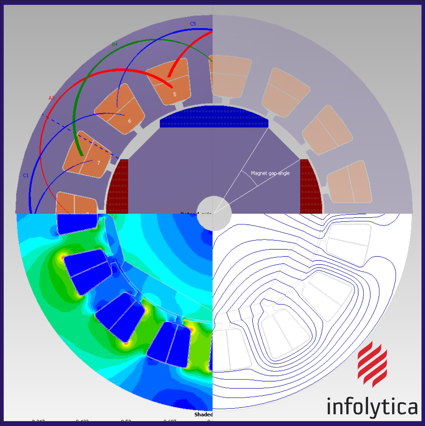
by Infolytica Corporation, © Copyrights
Design and development of very complex magnetic circuits can be aided with numerical methods such as finite-element modelling (FEM). It is possible to perform numerical modelling in 1D, 2D, 3D, as well as variation in time and coupled with other physical phenomena, such as mechanical forces and heat dissipation (multiphysics simulation).
Electromagnetic circuit is represented by a suitable geometry, reflecting the real design of a prototype or a product. Electromagnetic excitations can be assigned to windings (currents and voltages) and/or to permanent magnets. Material properties are also assigned to each component, with appropriate power loss mechanism (if required).
FEM is extremely useful in modelling complex mechanical structures, because it can accurately calculate complicated electromagnetic effects such as eddy currents, skin effect, proximity loss, magnetic saturation, magnetic coupling, leakage inductance, magnetic force, torque ripple, efficiency, heat dissipation, and so on.38)39)
However, certain non-linear effects (non-single-valued hysteresis loop, complex anisotropy of grain-oriented electrical steel) and mechanical arrangements (thin laminations in magnetic cores of transformers) cannot be accurately modelled or represented without some linearising or homogenising assumptions.40)
Nevertheless, the achievable accuracy of simulations can be very high, and allows rapid optimisation of design, because calculations can be programmed to be carried out in an automated way, in order to find the best design compromises for a given structure, without the need for initial prototyping.41)42)
Frequency implications
Depending on application, magnetic circuits need to operate at various frequencies, and the magnetic cores (as well as windings) must be designed appropriately for the given frequency bandwidth.
DC magnetic circuit

For DC current, or very slowly varying such that the eddy currents are not detrimental, the cores can be made of a solid alloy.
For example, magnetic cores of DC electromagnets can be made from solid steel (not laminated), because its permeability is sufficiently high, eddy currents are not an issue, and the solid steel can withstand large mechanical forces acting on the core.44)

However, in DC motors and generators, even though the input or output currents might be constant, but the parts of the magnetic circuit can be sequentially energised and de-energised at a quite rapid rate, thus making it behaving as AC locally.
Under such conditions losses due to eddy currents cannot be neglected and the magnetic cores must be also laminated in the same way as they are for AC machines.
AC magnetic circuit for low frequencies

Magnetic circuits for low and power frequencies (e.g. 50/60 Hz) are laminated in order to suppress the eddy currents.45)
The thickness of laminations is dictated mainly by the frequency of interest, due to the skin depth, but also by the available technology for manufacturing laminations.
Typical non-oriented electrical steel has thickness between 0.3-0.65 mm (depending on the grade), and grain-oriented between 0.23-0.35 mm. However, there are also “thin grades” of electrical steels with thickness as low as 0.1 mm, suitable for operation at frequencies above 50/60 Hz.
Amorphous and nanocrystalline ribbons have thickness at the order of 0.015-0.050 mm (15-50 μm), dictated by the rapid cooling requirements during making of the ribbons in the amorphous state.46)
Smaller thickness is difficult to achieve with conventional technology, and therefore for even higher frequencies (above 50 kHz) laminations are typically not used.
AC magnetic circuit for high frequencies
In the frequency range 20 kHz and above laminations are often replaced by cores made out of powder, with particle sizes down to nanometres.
At even higher frequencies, beyond 100 kHz soft ferrite materials are widely used for magnetic circuits. Ferrites based on iron oxides have very high resistivity, which inherently reduces eddy currents as compared to solid-metal alloys.
Different grades of ferrites are available, optimised for MHz and even GHz frequencies. However, at such high frequencies the flow of energy is constrained by waveguides, rather than “magnetic conduits” as such.

S. Zurek, E-Magnetica.pl, CC-BY-4.0